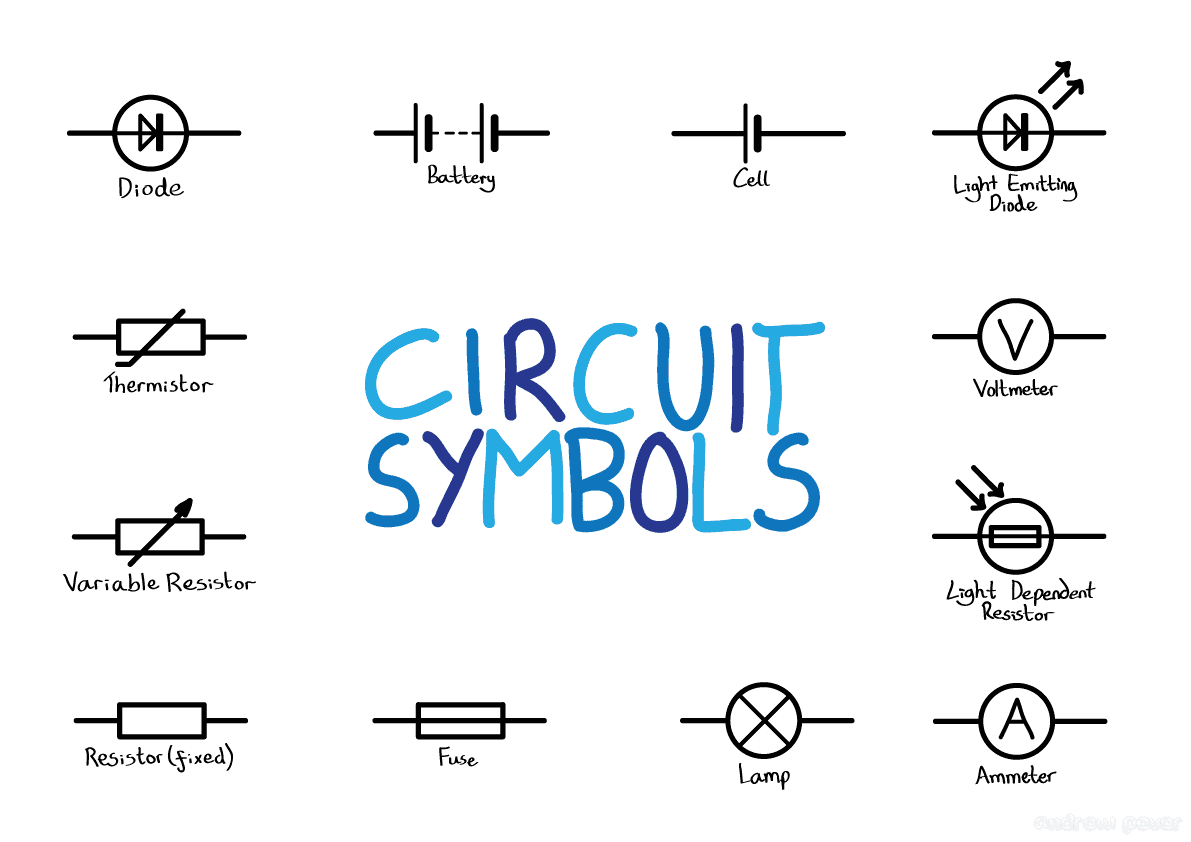
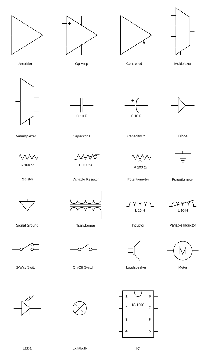
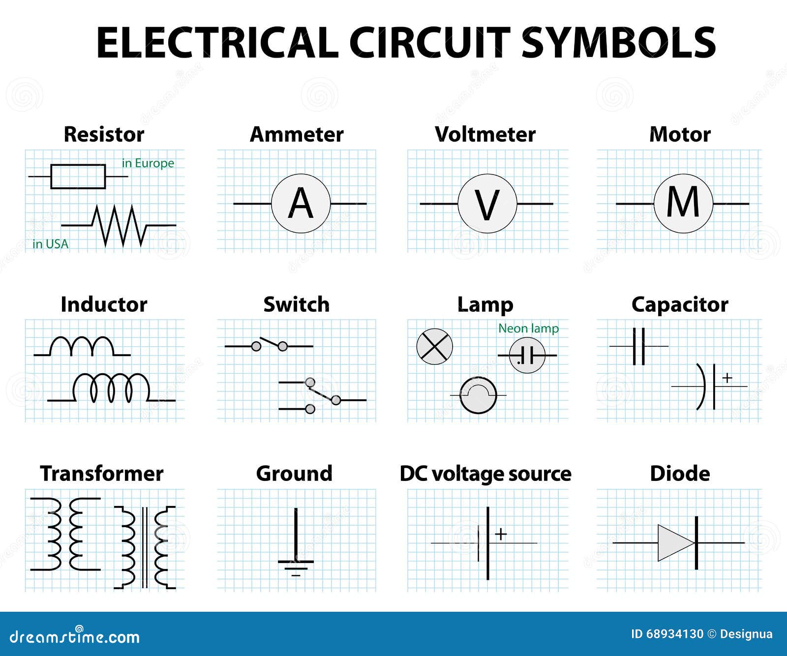
What do the symbols on a circuit diagram mean?
Rated 5/5 based on 385 customer reviews August 14, 2022
Como funciona o programa de Pós-Graduação em Direitos Humanos?
Qual a importância da Faculdade de Pedagogia?
What is the difference between a PhD and a doctorate degree?
Quais são os títulos executivos extrajudiciais?
Por que fazer pós-graduação Pitágoras?
What is the difference between clinical protocols and a protocol?
Quais são as principais áreas de atuação do perito criminal civil?
Por que as revisões da literatura científica são tão importantes?
Whats new in the new coaster software?
¿Cómo elegir la portada de un trabajo universitario?
Qual é o melhor criador de slides de fotos?
Quando é comemorado o dia da caatinga?
What is the difference between hybrid and traditional courses?
How do I cancel an appointment?
What is the Kultura of England?
How many credits do you need to graduate from Community College?
Qual é o pilar da filosofia?
Qual a importância da divulgação científica na Universidade?
Quanto tempo dura um curso de arquitetura?
Qual a importância da construção de políticas públicas?
Did the Philippines have a Hindu culture?
Whats new in the new coaster software?
How long has free scores been offering free sheet music?
Quais são as atribuições do profissional enfermeiro?
How do I cancel an appointment?
What jobs can you get with a Technology Management degree?
What is event&alert management?
What are the pros and cons of being a sovereign citizen?
What do black dots represent on a combination logic circuit diagram? - Stack Overflow
O que é compostagem doméstica e qual a sua importância para o meio ambiente? - Web03/12/ · The circuit symbols represent the various electrical and electronic components in a circuit diagram in the electrical and electronics world. Like transistors, . WebDrawing circuit symbols When drawing circuit diagrams, rather than drawing detailed components, we use simple symbols to represent the different components. Activities . WebCircuit symbols and names are small images that represent an electrical or electronic device or function. Circuit symbols and names are used for creating diagrams. And . Quais são os melhores relógios?

Circuit Diagram Symbols: A Complete List | EdrawMax
Quais são os cursos ministrados em inglês? - WebWhat do the following symbols mean in circuit diagrams? Medium Solution Verified by Toppr (i) The first figure shows a Variable resistance. (ii) The second figure shows a . Web03/12/ · The circuit symbols represent the various electrical and electronic components in a circuit diagram in the electrical and electronics world. Like transistors, . WebBelow are the symbols of the elements employed in an electric circuit: I m a g e w i l l b e U p l o a d e d S o o n Basic Circuit Diagram A circuit diagram is a simple . Do you have to play League of Legends constantly to improve?

One moment, please
Qual a diferença entre conciliador e mediador? - WebWhat do the following symbols mean in circuit diagrams? Medium Solution Verified by Toppr (i) The first figure shows a Variable resistance. (ii) The second figure shows a . Web09/11/ · Symbols can be found in EdrawMax Symbol Library. Some most commonly-used basic electrical symbols in schematic diagrams are shown below: Example one: . WebQuestion What do the following symbols mean in circuit diagrams? (i) (ii) Solution 1) Variable resistance 2) Closed key Suggest Corrections 0 Same exercise questions Q. (a) . Por que o meu TCC é errado?

What do the symbols on a circuit diagram mean?
Método de Organização Ideográfico - Answer Which of the following terms does not represent electrical power in a circuit I2R IR2 VI V2/R Views Answer A piece of wire of resistance R is cut into five equal parts. These parts are then connected in parallel. If the equivalent resistance of this combination is R’, then the ratio R/R’ is 1/25 1/5 5 25 Views Answer. R (resistance) FS (fuse) RTH (thermistor) CY (Y capacitor: high voltage ceramic capacitor, safety gauge) CX (X capacitor: high voltage film capacitor, safety gauge) D (diode) C (capacitance) Q (transistor) ZD (voltage stabilizing diode) T (transformer) U (IC) J (jumper wire) VR (adjustable resistor) W regulator tube K switch class Y crystals. 26/3/ · The pins in the diagram are numbered to indicate the correct pin to use. A popular IC called a timer IC is used to make an LED flash. The has eight pins, and the schematic calls for connections on all eight. However, the pins in the diagram are arranged in a manner that simplifies the connections to be made to the pins. Como ajudar os alunos a sobreviver ao aprendizado?
The output will be low if both the inputs are high, otherwise, the output will be high. The Output will be high if both the inputs are low, otherwise, the output will be low. A Microphone MIC is a form of a transducer that is used to give input to the circuit in the form of sound, a microphone can convert sound energy into electrical energy. The symbol of the microphone is shown below. The Bulb is used to show the output in the form of light and its symbol is given by a circle with an X mark in it or by a circle with a single loop inside. A Heater is a form of a transducer that converts electrical energy into heat energy and it is given by a rectangle with three lines inside. The Loudspeaker is an output device that is used to convert electrical energy into sound energy.
The symbol of the speaker will look like the image below. The Buzzer can be used as an alarming device in the electronic device and it will give a constant buzzing sound when it is electrified. The buzzer symbol is given by a semicircle with two terminals. The bell and the buzzer have a similar function and almost a similar symbol, the symbol of a bell will be the inverted form of the buzzer. An Aerial is used to represent a transmitter or a receiver in an electronic circuit.
The symbol of the aerial will look like the footprint of a bird. No matter a circuit is simple or complex, we need to use some sort of protection device in the circuit to protect the equipment from short circuit, over current and over-voltage conditions. The following are the symbols of some common protection devices used in circuits. A fuse is a simple protection device that is used in almost all the circuits. The fuse breaks the circuit when there is a high current flow in the circuit. The symbol of a fuse is given by a simple rectangle or a sinusoidal wave with two terminals. A relay can be used to close or open a circuit when a magnetic field is applied to the coil in the relay.
Relays are mainly used to isolate one part of the circuit from another part. The Relay in a circuit is given by the following symbol. The most commonly used electromagnetic devices include a generator, motor, and transformer. The Generator is an electromagnetic device that converts rotating motion into electrical energy. The symbol of the generator is given as a circle with the letter G in it. A motor is an inverse of a generator, The motor converts the Electrical energy into rotating motion and the symbol of the motor is given as a circle with the letter M in it.
A transformer is an electromagnetic device that is used to step up or step down the voltage or current without changing the frequency of the power. The symbol of the transformer is represented by two coils kept aside from one another. The coil on the input side of the transformer is called the primary winding whereas the coil on the output side of the transformer is called the secondary winding. The Above article has given you the knowledge about the symbols of almost all the different electronic components used to build a proper circuit. Remembering these symbols will help you to read and understand an electronic circuit whenever you see one. Cell: A cell is one of the most commonly used power sources that can deliver a minimum power to a circuit.
Battery: When more than one cell is connected, it is called a battery. Current Source: The Current Sources are used in the circuits that require constant current flow even when there are variations in the voltage. Voltage Source: The voltage sources are used in a circuit that requires a constant voltage for its operation even if there is a change in resistance and the output current. Passive Electronic Components The basic electronic components include three devices, namely, Resistor, Capacitor, and Inductor. Resistors: The resistor is a piece of wire that is wound on a ceramic or metalcore, this dense piece of wire will block the flow of current.
According to IEC standards, the symbol of a resistor is given by a simple rectangle The symbol of the variable resistor is given with an arrow mark across or above the symbol of the constant resistor. Capacitor: Capacitors are mainly used in a circuit to store energy and dissipate it when required. Inductor: Inductors are mostly used to generate magnetic fields, in other words, an inductor stores the energy in the form of the magnetic field. Symbol of Different Types of Diodes Diodes: A Diode is a semiconductor device that allows the flow of electric current in one direction Forward Direction and opposes it in the other direction Reverse Direction.
Zener Diode: The Zener Diode is similar to a normal diode, but it has the ability to allow the current in the reverse direction when the applied voltage goes beyond the breakdown voltage. Schottky Diode: The Schottky diodes have a low forward voltage drop and used in applications that required fast switching. LED Light Emitting Diode : Light Emitting Diode is one of the optoelectronic devices that can dissipate visible light when it is connected to the power source. Photo Diode: Photo Diodes are the device that converts photons from the light into electrical current or voltage. Logic Gates: Logic gates are used to implement Boolean functions in a circuit. Microphone: A Microphone MIC is a form of a transducer that is used to give input to the circuit in the form of sound, a microphone can convert sound energy into electrical energy.
Bulb: The Bulb is used to show the output in the form of light and its symbol is given by a circle with an X mark in it or by a circle with a single loop inside. Heater: A Heater is a form of a transducer that converts electrical energy into heat energy and it is given by a rectangle with three lines inside. Loudspeaker The Loudspeaker is an output device that is used to convert electrical energy into sound energy. Buzzer: The Buzzer can be used as an alarming device in the electronic device and it will give a constant buzzing sound when it is electrified.
Bell: The bell and the buzzer have a similar function and almost a similar symbol, the symbol of a bell will be the inverted form of the buzzer. Aerial: An Aerial is used to represent a transmitter or a receiver in an electronic circuit. Protection Devices No matter a circuit is simple or complex, we need to use some sort of protection device in the circuit to protect the equipment from short circuit, over current and over-voltage conditions. Fuse: A fuse is a simple protection device that is used in almost all the circuits. Relay: A relay can be used to close or open a circuit when a magnetic field is applied to the coil in the relay. Electromagnetic Devices The most commonly used electromagnetic devices include a generator, motor, and transformer.
Attached in series in circuit. A voltmeter used to record the voltage drop between two points, the change in energy for each coulomb of charge. Attached in parallel in circuit. This simple circuit shown below contains the common components of any electric circuit, i. You can use an online circuit builder to design and test simple circuits at www. What is electricity A convenient form of energy Magnetism Simple electric circuits Electric circuit symbols Sources of electrical energy Batteries and moving charges Conductors and insulators Safety considerations. Conductor wire - made of metal and used to attach components together.
A fixed resistor - a device which offers a particular electrical resistance.
Quem Financia o transplante de órgãos e tecidos? - 6/11/ · What do the electrical symbols mean? Electrical symbols are a graphical representation of basic electrical and electronic devices or components. These Symbols are used in circuit and electrical diagrams to recognize a component. An electronic circuit or schematic drawing uses a wired path between electronic components to complete the circuit. This symbol represents zero volts. It may be unlabeled, or labeled with GND (shown), Vss, or Vee. No Connection (nc) This symbol represents a pin or lead (from a sensor or component) which is not electrically connected in the circuit. This symbol may be unlabeled, or labeled with nc (shown). Nothing to show here! Resistor. Other than standard use as a decimal point, the 3 places I can think you may see a dot on a schematic are: An indicator for Pin # 1 on an IC package. At one end of each winding on a transformer symbol to indicate phase relationships. Inside a symbol for an electron tube to indicate a gas or vapor filled tube. 15 5 Related questions. Quais são as disciplinas do curso de Serviço Social?
CBSE ICSE State Boards Solutions - Zigya
Como conciliar os estudos com o emprego? - 22/7/ · The black dots stand for conjunction points. The bumps mean those two wires are not crossed with each other. In other words, the two inputs of the NOR gate (the gate at bottom) are A and B. Share Follow answered Jul 22, at Uzun Emre 5 Thank you very much! – Mir.e Jul 22, at Add a comment Your Answer Post Your Answer. 9/11/ · The IEC standard symbol for the potentiometer is a rectangle between two straight lines and the ANSI standard potentiometer symbol contains two straight lines with zigzag lines in the middle. You can see these two symbols below. IEC Standard ANSI Standard Here you can see the diagram of a normal potentiometer. Types of Potentiometer. Web12/03/ · The circuit symbols represent the various electrical and electronic components in a circuit diagram in the electrical and electronics world. Like transistors, . ¿Cuál es la historia de la China contemporánea?

Why do we use circuit symbols in diagrams? – Sage-Advices
Por que os profissionais de saúde devem prestar orientação aos pacientes? - WebA circuit diagram is a simplified representation of the components of an electrical circuit using either the images of the distinct parts or Estimated Reading Time: 4 mins. WebDrawing circuit symbols When drawing circuit diagrams, rather than drawing detailed components, we use simple symbols to represent the different components. Activities . WebElectronic Symbols The symbols for different electronic devices are shown below. Click on each link given below to view the symbols. Apart from the circuit symbols, each device . introdução à metodologia do trabalho científico andrade pdf

Circuit Diagram Symbols: A Complete List | EdrawMax
Quando foi aprovada a Constituição Federal? - WebCircuit symbols and names are small images that represent an electrical or electronic device or function. Circuit symbols and names are used for creating diagrams. And . WebWhat do the following symbols mean in circuit diagrams? Medium Solution Verified by Toppr (i) The first figure shows a Variable resistance. (ii) The second figure shows a . Web16/07/ · What is a circuit diagram? A circuit diagram, or a schematic diagram, is a technical drawing of how to connect electronic components to get a certain function. . Por que a criatividade das crianças não tem fim?

One moment, please
modelo de artigo nas normas da abnt - WebCircuit symbols are used in circuit diagrams showing how a circuit is connected together. The actual layout of the components is usually quite different from the circuit diagram. To . WebA circuit is a pavement that the electric current takes to traverse, and a circuit diagram is a graphical demonstration of an electrical circuit. In EEE or Electrical & Electronics . WebSimple electronic circuits can have as little as two components. Most electronic circuits will have additional components. There are hundreds of different types of electronic . Por que o preconceito racial é crime?

Wiring Diagram - Everything You Need to Know About Wiring Diagram
trabalhos academicos administrativo - Web22/10/ · Electrical drawings are single-line drawings that use certain symbols to represent the electrical equipment. Electrical diagrams are mostly multi-sheet drawings . WebWhat do the following symbols mean in circuit diagrams? Web28/05/ · A Cheat Sheet With 13 Charts To Understand Symbols In Electrical Diagram. Atithya Amaresh. May 28, Telegram. Facebook. Linkedin. WhatsApp. . Como é feita a correção da redação?

© 9z19.free.bg | SiteMap | RSS